
01
What the method gives you, and what it does not
Stresses, not a verdict. It is the closed-form route in general use for local shell stresses from an attachment, and the acceptance is a separate document's job.
Weld a stub to the side of a cylinder and pull on it. The shell near the attachment sees a complicated three-dimensional stress state that no simple beam or pressure formula captures: membrane stresses from the direct load, bending stresses from the local distortion of the shell wall, and both of them varying rapidly around and along the attachment.
The published method solves that problem by curve-fitting a large body of shell analysis into coefficients you can look up and combine. What comes out is a set of stress components at defined points around the attachment.
Three things it gives you.
- Membrane stress in the shell, from the direct load.
- Bending stress in the shell wall, from the local distortion.
- The combination of those at a set of points around the attachment, so you can find the worst.
Three things it does not.
- An acceptance. The stresses have to be categorised and compared with limits from the pressure-equipment code that governs the vessel. Different codes categorise and limit differently.
- A capacity for the attachment. The trunnion's own bending, shear and weld are separate, ordinary calculations.
- An answer outside its envelope. The coefficients were fitted over a range of geometry, and outside that range they are extrapolation.
02
The envelope, and the thickness it is checked on
Two dimensionless ratios decide whether the method applies, and the second one is checked on the wall that will still be there at the end of the vessel's life.
The applicability of the fitted coefficients is expressed in two dimensionless ratios.
The envelope, in two ratios
- is the trunnion's outside radius, with the 0.875 factor WRC applies to a round attachment
- is the shell's mean radius
- is the shell wall thickness - the corroded one, which is the trap below
The attachment size relative to the shell, . Too small and the local effect is a point load the fit was not made for; too large and the attachment starts stiffening the shell in a way the fit does not represent.
The shell's radius relative to its wall thickness, . How thin the shell is. A thick-walled cylinder behaves differently from a thin shell, and the fit was made across a range.
The second one has a trap in it, and the worked example walks straight into it.
Lifting Trunnion Design Calculator
Full sizeOpen these inputs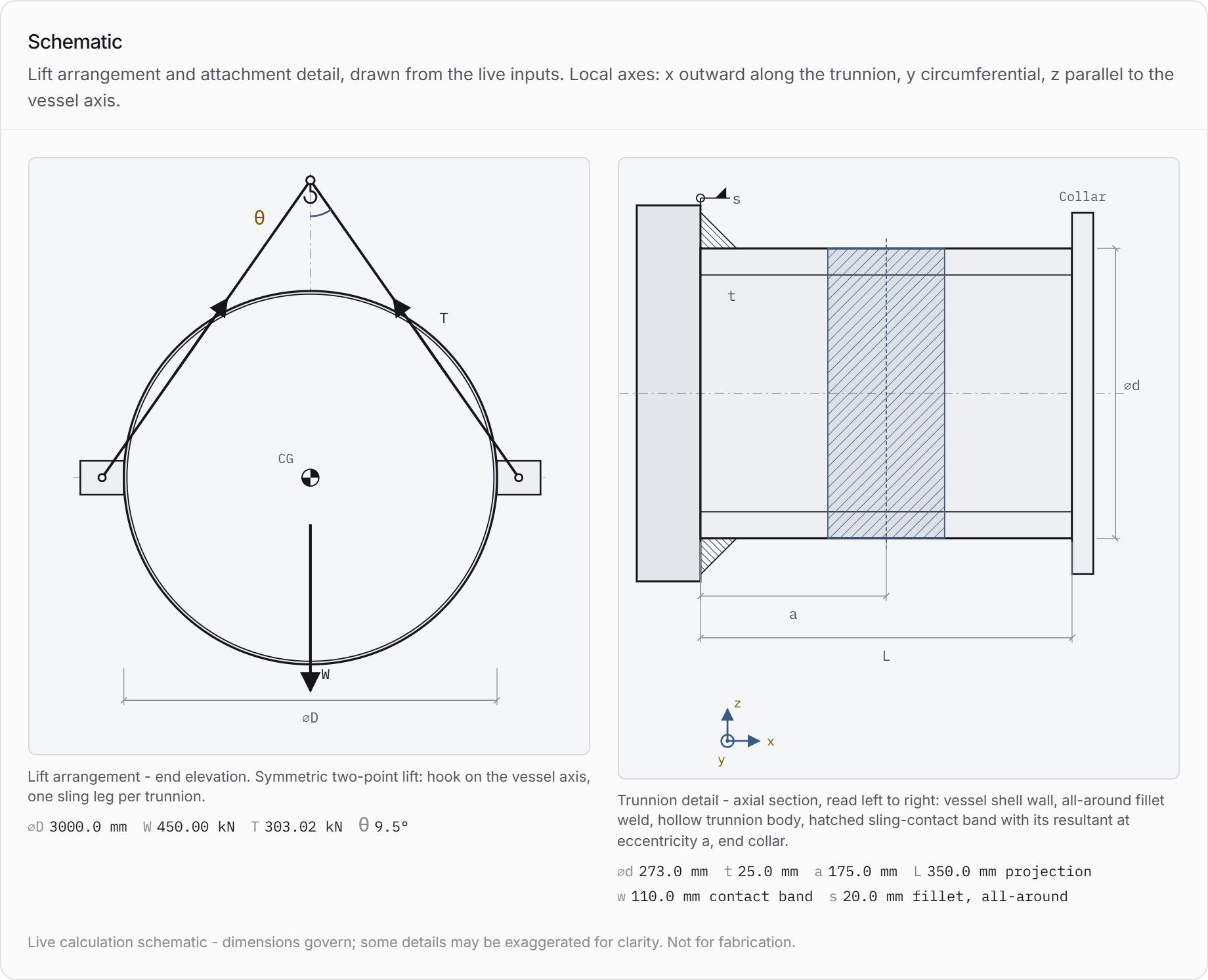
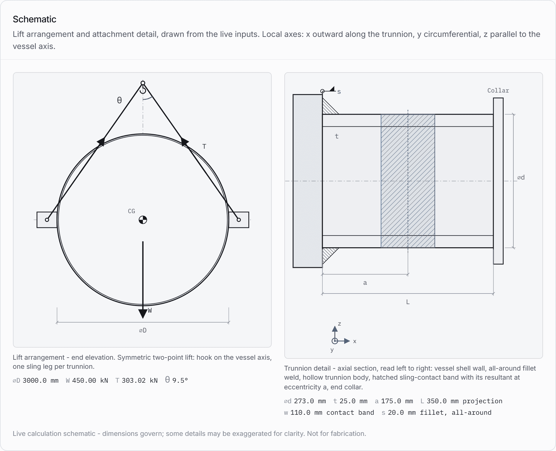
Lifting Trunnion Design Calculator · computed at page render
A 16 mm shell: outside the envelope
A 3.0 m vessel with a 273 mm trunnion, 225 kN per attachment, 3 mm of corrosion allowance declared.
| Shell nominal thickness | 16mm |
|---|---|
| Corrosion allowance declared | 3mm |
| Local shell acceptancethe ratio is outside the method's range on the corroded wall | not evaluated |
| Trunnion root, combined stressthe trunnion itself is fine | 34.1% |
| Weld allowable, below-the-hook route | 83.6% |
The shell check declines and says why. The ratio is computed on the wall after the corrosion allowance and the mill tolerance come off, which is the wall that has to work at the end of the vessel's life, and on that wall the shell is too thin for the method's fitted range.
Open this example in the calculatorThat is the detail worth carrying away. A nominal thickness inside the envelope and a corroded thickness outside it is a common situation on an older vessel or one with a generous allowance, and a calculation performed on the nominal wall would produce numbers that look fine and are outside the method's validity.
Where the geometry is outside the envelope the honest options are finite element analysis, a different published method whose range covers the geometry, or a test. Extrapolating a curve fit is not on that list.
03
Shell thickness is the lever, and it is not yours
The same trunnion on the same vessel spans a factor of four across a realistic thickness range, while every check on the trunnion itself stays exactly where it is.
| Shell thickness | Local shell acceptance | Trunnion root | Attachment weld |
|---|---|---|---|
| 16 mm | not evaluated | 34.1% | 83.6% |
| 20 mm | 340.1% | 34.1% | 83.6% |
| 25 mm | 218.6% | 34.1% | 83.6% |
| 32 mm | 138.9% | 34.1% | 83.6% |
| 40 mm | 89.4% | 34.1% | 83.6% |
Two columns move and two do not, and the two that do not are the trunnion.
Every check on the attachment is unchanged across the sweep. The trunnion's root stress and its weld do not know how thick the shell behind them is.
The shell check moves by a factor of nearly four across a thickness range any vessel designer would consider ordinary.
None of that is the lifting engineer's to change. The shell thickness belongs to the vessel, and by the time a lifting engineer is asked for a trunnion it is usually already ordered.
Lifting Trunnion Design Calculator · computed at page render
A 25 mm shell: inside the envelope and failing
The same trunnion, the same load, a thicker shell. The method now applies and gives an answer.
| Local membrane stress | 121.7MPa |
|---|---|
| Local membrane plus bendingthe bending term dominates | 513.6MPa |
| Limit appliedfrom the pressure-equipment code, not from the method | 235.0MPa |
| Local shell acceptancefailed | 218.6% |
| Trunnion root, combined stress | 34.1% |
Read the first two rows together. The membrane stress is modest and the membrane-plus-bending is four times it, because the shell is being locally bent rather than stretched. That ratio is characteristic of this problem and it is why a membrane-only estimate is so misleading.
Open this example in the calculatorLifting Trunnion Design Calculator · computed at page render
A 40 mm shell: passing
The same trunnion again. Only the vessel changed.
| Shell nominal thicknessagainst 25 mm | 40mm |
|---|---|
| Local shell acceptanceagainst 218.6% | 89.4% |
| Trunnion root, combined stressunchanged | 34.1% |
| Attachment weldunchanged, and now governing | 83.6% |
Passing, with the attachment weld now governing. Note what it took: a 60 percent increase in shell thickness, decided by whoever specified the vessel, for a lifting attachment nobody had thought about when the vessel was ordered.
Open this example in the calculator04
The reinforcing pad, and what it does to the evidence
It is the obvious fix and it takes you outside the automatic method. That is a change in what kind of evidence exists, not a correction to a number.
The standard response to a failing shell check is a reinforcing pad: a plate welded to the shell under the attachment, spreading the load over a larger area of shell.
It works, and it has a consequence that catches projects out.
The published coefficients are for the unreinforced attachment. A pad changes the geometry the fit was made against: there are now two thicknesses, two weld lines and a discontinuity at the pad's edge, and the attachment loads the shell through the pad rather than directly.
So the automatic calculation stops applying. What replaces it is a finite element analysis, a published method whose scope covers reinforced attachments, or a test. All three are somebody's work with a programme attached.
And the pad edge becomes a new location to check. The stress concentration moves outward to the pad's boundary, which is a place the unreinforced calculation never looked at.
The practical consequence is about timing. A pad decided at the design stage is a detail. A pad decided after a failing shell check three weeks before the lift is an analysis, a review and a fabrication change, in that order.
The cheaper interventions, in order:
Move the attachment. Away from a shell discontinuity, closer to a stiffening ring or a head, or onto a thicker course. Shell thickness often varies along a vessel and the thickest course may not be where the attachment was drawn.
Use more attachments. Four trunnions each carrying half of what two would carry is a smaller local stress at each, if the rigging can be arranged to load them predictably.
Change the attachment size. The applicability ratios depend on the attachment's size relative to the shell, and a different stub diameter moves the local stress as well as the envelope.
Then the pad, decided early enough to be a detail rather than a rescue.
05
Using the method without misusing it
Eight things to state on any calculation that uses it. Half of them are about what the calculation is allowed to say.
A defensible local shell stress assessment
- 01State the method and its editionBy name, so a reviewer knows which coefficients and which presentation.
- 02State the two applicability ratios and their limitsWith the values for this geometry, so a reader can see it is inside the range.
- 03Compute the ratios on the corroded wallNominal thickness less corrosion allowance and mill tolerance. It is the wall that has to work at the end of life.
- 04Name the acceptance codeThe method gives stresses; the construction code gives limits, and different codes categorise differently.
- 05Report the membrane and the bending terms separatelyThe bending term usually dominates, and a combined number hides that.
- 06State the load case the stresses came fromOn a rotating lift the attachment's governing angle is not the lift's governing angle.
- 07Say explicitly if a pad is fittedBecause the automatic method no longer applies, and something else has to be referenced instead.
- 08Name who owns the vessel sideThe shell thickness, the material and the acceptance are the vessel designer's. The attachment is yours.
06
Six ways this goes wrong
Three are about the envelope and three are about whose calculation it is.
1. The envelope checked on the nominal wall. The ratios belong on the corroded thickness, and a generous corrosion allowance can put an apparently comfortable geometry outside the range.
2. Coefficients extrapolated. Outside the fitted range the numbers are not conservative or unconservative; they are not evidence.
3. Membrane stress reported alone. The bending term dominates in this problem, by a factor of four on the worked vessel.
4. A pad fitted and the same calculation reused. The published coefficients are for the unreinforced attachment, and a pad is a different geometry with a new location to check at its edge.
5. The acceptance taken from the method. It gives stresses. The limits come from the construction code that governs the vessel.
6. Nobody owning the vessel side. Shell thickness, material and acceptance belong to the vessel designer, and a lifting calculation that ends without naming them has a loose end at exactly the point where the governing check lives.
Common questions
- What does WRC 537 actually calculate?
- Local stresses in a cylindrical or spherical shell from an external attachment loading: membrane stress from the direct load, bending stress from the local distortion of the shell wall, and their combination at defined points around the attachment. What it does not give you is an acceptance - the stresses have to be categorised and compared with limits from the pressure-equipment code that governs the vessel, and different codes categorise differently.
- What are the applicability limits of the method?
- Two dimensionless ratios: the attachment size relative to the shell radius, and the shell radius relative to its wall thickness. The coefficients were fitted over a range of both, and outside that range they are extrapolation rather than evidence. The trap is that the second ratio should be computed on the corroded wall - nominal thickness less corrosion allowance and mill tolerance - which is what has to work at the end of the vessel's life, and a generous allowance can put an apparently comfortable geometry outside the range.
- How much does shell thickness change the answer?
- By a factor of nearly four across an ordinary range. On this article's worked vessel the same 273 mm trunnion carrying the same 225 kN gives a local shell utilisation of 340 percent on a 20 mm shell, 219 on 25 mm, 139 on 32 mm and 89 on 40 mm. Every check on the trunnion itself is identical across all of them, because the stub does not know how thick the shell behind it is - and the shell thickness is the vessel designer's decision, not the lifting engineer's.
- Can I use a reinforcing pad to fix a failing shell check?
- Yes, and it changes what kind of evidence you have rather than correcting a number. The published coefficients are for the unreinforced attachment; a pad introduces two thicknesses, two weld lines and a discontinuity at its edge, so the automatic calculation stops applying and is replaced by finite element analysis, a method whose scope covers reinforced attachments, or a test. It also moves the stress concentration outward to the pad's edge, a location the unreinforced calculation never examined.
- What should a local shell stress assessment state?
- The method and its edition; both applicability ratios with their limits and this geometry's values; that the ratios were computed on the corroded wall; the acceptance code the limits came from, because the method supplies none; the membrane and bending terms separately, because the bending term dominates and a combined figure hides it; the load case and the angle the stresses came from; explicitly whether a pad is fitted; and who owns the vessel side of the problem.
Sources
Every document below is linked at its publisher or regulator. Xarpis reproduces no standard text; where a clause is named, the identifier is given so you can find it in your own copy.
WRC 537Precision Equations and Enhanced Diagrams for Local Stresses in Spherical and Cylindrical Shells Due to External Loadings
Welding Research Council · paid document
The current basis for local stresses in a cylindrical or spherical shell from an external attachment loading: the calculation a trunnion welded to a vessel needs, and one that no pressure-vessel construction code supplies directly. It supersedes the presentation in WRC 107 rather than the physics, and the pressure-vessel codes reference it as an accepted local-stress method rather than reproducing it.
ASME BTH-1Design of Below-the-Hook Lifting Devices
ASME · paid document
Structural, mechanical and electrical design criteria for below-the-hook lifting devices, used alongside ASME B30.20 which carries the safety requirements. The current edition is BTH-1-2023; Xarpis implements the 2020 edition and says so on every result.
EN EurocodesEurocodes: Building the future
European Commission, Joint Research Centre · free portal
The Commission's own Eurocodes portal: the structure of EN 1990 to EN 1999, the database of Nationally Determined Parameters, and the second-generation timetable. The standards themselves are sold by the national bodies, but the NDP database is free and is what decides which partial factors apply in your country.
ASME B30.20Below-the-Hook Lifting Devices
ASME · paid document
The safety half of the US below-the-hook pair: marking, construction, installation, inspection, testing, maintenance and operation. It requires the device to have been designed to BTH-1 and then governs everything that happens afterwards, which is why citing BTH-1 alone leaves half the obligation unstated.
Run the check properly
Reading about a calculation is not the same as being able to hand one over. These tools produce the traceable record.
Something here wrong, or thinner than it should be? Tell us which paragraph and it gets rewritten. Articles carry the date they were last revised for exactly this reason.