
01
Two different jobs, and only one of them is arithmetic
Computing a number is the easy half. Producing something a reviewer can audit without you in the room is the half that takes the work, and it is not something a calculation box can do.
Computing. Give it inputs, get a number. Fast, useful, and for the classical identities in rigging it is genuinely easy to get right. Most free calculators do this well.
Proving. Producing an artefact that says what was checked, what was not, where every input came from, which design route applies, what the allowables are and why, and what stayed outside the validated scope. That is a document rather than a number, and it is what somebody accepts.
Almost every argument about calculators is really an argument about which of those two jobs is being discussed. A free tool that computes correctly is not deficient; it is doing the first job.
01What are you going to do with the answer?
- Decide something in the next five minutes
- A free calculator, or a pencil, is the right tool. In a meeting, on site, deciding whether an approach is worth pursuing. Speed beats provenance here.
- Hand it to somebody who has to accept it
- A record with provenance, scope and a route. A number with no source cannot be reviewed, and being right is not the same as being reviewable.
- Put it in a lift plan
- A record, and the plan carries its reference. Somebody will read that plan without you available.
02Does the tool tell you what it did NOT check?
- Yes, explicitly
- That is the single best signal there is. A missing check and a passing check look identical unless a tool says so.
- No
- Then you have to know the check list yourself. Which is fine if you do. It is not fine if the tool is standing in for knowing it.
02
What a free calculator does well
The classical identities, and it does them exactly right. The worked sling calculation below is correct to as many figures as anybody needs.
Two legs at 45 degrees under a 8 t load, which is the single most-searched rigging calculation there is:
- Inward pull at each lift point: 39.2 kN
Free tools that do this are worth bookmarking. Sling tension, load angle factors, unit conversion, centre of gravity from component masses, simple beam reactions: all of them are classical, all of them are quick, and none of them needs a subscription.
The limit is not accuracy. It is scope. That leg tension arrives somewhere, and the somewhere is where the engineering was.
03
Where the free answer stops
At the sling. Everything the sling is attached to is a design, and a design is a set of checks against a route with declared allowables.
Lifting Lug Calculator · computed at page render
The padeye at the other end of that sling
The 55.5 kN from the free calculation, arriving at a padeye 45 degrees off its axis with a declared dynamic factor.
| Leg tension from the free calculationcorrect | 55.5kN |
|---|---|
| Design load after the declared dynamic factora factor the free calculator never asked about | 63.8kN |
| Net-section tension | 11.2% |
| Double-plane shear-out | 35.1% |
| Pin bearing on the lug | 23.7% |
| Fillet weld throat resultant | 80.7% |
Every one of these is a check the sling calculation had no way to reach, on a component it had no way to know about. Neither tool is wrong; they answer different questions, and only one of those questions is the design.
Open this example in the calculatorAnd this is the same padeye drawn by the tool that checked it, on the leg tension the free calculation produced:
Lifting Lug Calculator
Full sizeOpen these inputs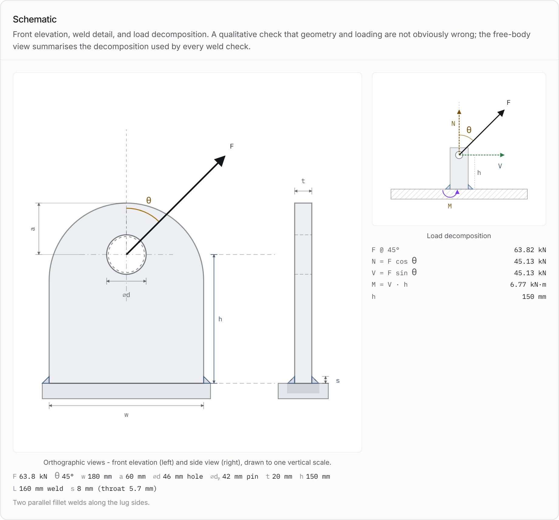
04
Judging any calculator, free or paid
Six questions. They apply to this site's tools exactly as they apply to anybody else's, and the answers are what should decide whether you use one.
Questions to ask of a calculation tool
- 01Does it say what it did not checkExplicitly, as a list. A missing check and a passing check look identical without it.
- 02Does it name the design route and editionBecause the allowables follow from it, and editions change.
- 03Can somebody see where each input came fromA record carries provenance. A results box carries values.
- 04Does it refuse where it shouldA tool that produces a number for a case it cannot handle is more dangerous than one that stops.
- 05Can the result be reproducedSame inputs, same version, same answer, and the version is visible.
- 06Is the output something a reviewer can holdA document with a date, a revision and a scope statement, not a screenshot.
Two of those are worth expanding, because they are the ones that separate tools.
Refusing where it should. A tool that computes something for every input is not more capable, it is less honest. Elsewhere on this site there are worked examples where an engine declines: a Canadian design route with no load factor declared, a shell stress method outside its geometric envelope, a European route above a cycle threshold. Each refusal is more useful than a number would have been, because the number would have been an invention.
Saying what it did not check. This is the one that catches spreadsheets and it catches web calculators equally. A padeye tool that omits shear-out prints exactly like one that includes it.
05
Where this site sits, stated plainly
Because an article like this written by a company selling calculators is worth nothing unless it says what its own tools do and do not do.
What is free here, with no account. A 2D frame and beam finite element pack, in full. Every calculator's methodology page, listing what each check is traceable to and what stays out of scope. Every article, including the worked examples with their engine-computed numbers, and every one of those examples opens in the calculator on exactly the inputs it used.
What is paid. The traceable, issuable report: the record with its inputs, its governing check, its source basis and its scope statement, in a form somebody can accept. That is the product, and this article's whole argument is that the record rather than the arithmetic is the thing worth paying for.
What these tools do not do. They do not invent a formula for a check with no traceable source; a check without one is marked as awaiting a source and computes nothing. They do not supply an allowable stress you have not declared or a design route has not established. They do not decide a load factor for a jurisdiction that has none. And they do not know about your particular vessel, structure or ground unless you tell them.
What that means for you. If you need a number, take it free. If you need something a third party will accept, the record is what you are buying, and you should judge it by the six questions above rather than by this paragraph.
And here is the thing being described, so the claim can be judged rather than taken. This is the record for the padeye above, complete and unwatermarked, in the article rather than behind a form:
padeye-8t-sling-rev-A.pdf
Lifting Lug Calculator · complete, unwatermarked
Lifting Lug Calculator report
Free calculator article - the padeye at the other end · Rev A
2026-09-16 02:08:03 UTC
SI (mm · kN · MPa)
Mechanics of Materials (user-supplied allowables)
Inputs summary
Design load
55.49 kN
Dynamic factor
1.15
Lifting angle
45°
Plate thickness
20.0 mm
Plate width
180.0 mm
Hole diameter
46.0 mm
Pin diameter
42.0 mm
Edge distance
60.0 mm
Corrosion allow.
0.0 mm
355.0 MPa
490.0 MPa
Allow. tension
213.0 MPa
Allow. shear
123.0 MPa
Allow. bearing
320.0 MPa
Offshore
No
Weld leg
8.0 mm
Weld length × count
160.0 mm × 2
Weld allow.
207.0 MPa
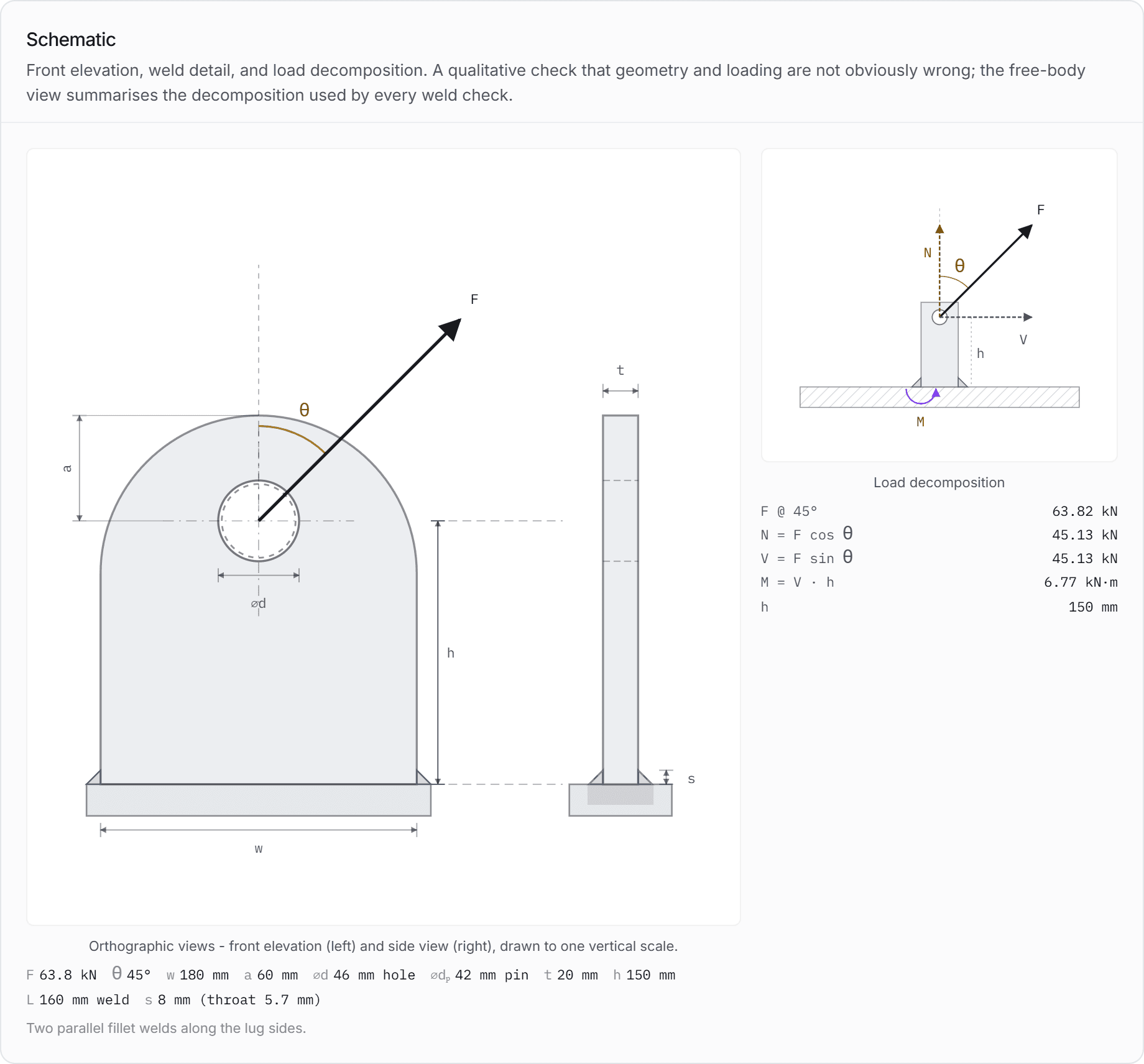
Schematic
Governing summary
Governing check
Fillet weld throat resultant (mechanics)
Utilisation
0.807 (80.7%)
Overall status
pass
FEA recommended
No
Primary checks - Mechanics of Materials
Governing utilisation is computed from these checks only.
| Check | Demand | Capacity | U | Status |
|---|---|---|---|---|
| Net-section tension (mechanics) | 23.81 MPa | 213.00 MPa | 0.112 | Pass |
| ||||
| Double-plane shear-out (mechanics) | 43.12 MPa | 123.00 MPa | 0.351 | Pass |
| ||||
| Pin bearing on lug (mechanics) | 75.97 MPa | 320.00 MPa | 0.237 | Pass |
| ||||
| Pin double shear (mechanics) | 23.03 MPa | 220.00 MPa | 0.105 | Pass |
| Fillet weld throat resultant (mechanics) | 167.05 MPa | 207.00 MPa | 0.807 | Pass |
| ||||
| Fillet weld von Mises throat stress (mechanics) | 237.56 MPa | 358.00 MPa | 0.664 | Pass |
| ||||
| Fillet weld strength - AISC 360-22 §J2.4 | 302.35 kN | 391.19 kN | 0.773 | Pass |
| ||||
| Base section combined stress (mechanics) | - | - | - | Info |
| ||||
Cross-checks (other frameworks)
Independent utilisations from the other methodology families, shown for comparison. Not included in the governing result.
| Check | Demand | Capacity | U | Status |
|---|---|---|---|---|
| Net-section tension - BTH-1 §3-3.3.1 | 63.82 kN | 222.24 kN | 0.287 | Pass |
| Single-plane fracture - BTH-1 §3-3.3.1 | 63.82 kN | 161.70 kN | 0.395 | Pass |
| ||||
| Double-plane shear-out - BTH-1 §3-3.3.1 | 63.82 kN | 169.83 kN | 0.376 | Pass |
| Pin bearing - BTH-1 §3-3.3.4 | 63.82 kN | 124.25 kN | 0.514 | Pass |
| ||||
| Fillet weld allowable - BTH-1 §3-3.4.3 | 167.05 MPa | 80.50 MPa | 2.075 | Fail |
| ||||
| Base section interaction - BTH-1 eq (3-35) | - | - | - | Info |
| ||||
| Base section critical stress - BTH-1 eq (3-37) | - | - | - | Info |
| ||||
| Base section shear - BTH-1 eq (3-28) | - | - | - | Info |
| ||||
| Pin-plate geometry - EC3 §3.13.1 | 0.950 | 1.000 | 0.950 | Pass |
| ||||
| Pin shear - EC3 §3.13.2 | 63.82 kN | 1064.02 kN | 0.060 | Pass |
| ||||
| Plate bearing - EC3 §3.13.2 | 63.82 kN | 447.30 kN | 0.143 | Pass |
| Pin bending - EC3 §3.13.2 | 0.54 kN·m | 6.98 kN·m | 0.078 | Pass |
| ||||
| Pin combined shear + bending - EC3 §3.13.2 | 0.010 | 1.000 | 0.010 | Pass |
| ||||
| Fillet weld - EN 1993-1-8 §4.5.3.2 directional method | 237.56 MPa | 435.56 MPa | 0.545 | Pass |
| ||||
| Fillet weld - EN 1993-1-8 §4.5.3.3 simplified method | 944.83 N/mm | 1422.30 N/mm | 0.664 | Pass |
| ||||
| Base section yield criterion - EN 1993-1-1 eq (6.1) | - | - | - | Info |
| ||||
| Dynamic amplification factor - DNV-ST-N001 §16 | 1.100× | - | - | Info |
| ||||
| Skew-load factor - DNV-ST-N001 §16 | 1.100× | - | - | Info |
| ||||
| Lift-point consequence factor - DNV-ST-N001 §16.8.3 | 1.300× | - | - | Info |
| ||||
Weld group - demand, section, and throat stresses
Lifting load at angle (in-plane) is decomposed at the weld centroid into a normal component , a transverse shear , and an in-plane bending moment , where is the pin-to-weld centroid distance. Topology: parallel side welds (two line welds along the lug sides).
| Demand decomposition | ||
|---|---|---|
| Quantity | Symbol | Value |
| Lifting angle | 45.0° | |
| Lever arm | 150.0 mm | |
| Applied load | 63.82 kN | |
| Normal component | 45.13 kN | |
| Transverse shear | 45.13 kN | |
| Bending moment | 6.769 kN·m | |
| Section properties | ||
|---|---|---|
| Quantity | Symbol | Value |
| Leg size | 8.0 mm | |
| Throat | 5.7 mm | |
| Total weld length | 320.0 mm | |
| Throat area | 1810 mm² | |
| Section modulus | 48265 mm³ | |
| Throat stresses | ||
|---|---|---|
| Quantity | Symbol | Value |
| Normal (⊥) | 116.80 MPa | |
| Transverse shear | 116.80 MPa | |
| Longitudinal shear | 24.93 MPa | |
| Equivalent (vM) | 237.56 MPa | |
| Resultant |R| | 167.05 MPa | |
Allow. shear (τ)
207.0 MPa
Allow. tension (σ)
358.0 MPa
483.0 MPa
Assumptions
- Geometry is a single-plate lug / padeye without cheek plates. Cheek-plate configurations are out of scope for v1 and require detailed analysis.
- The pin-region checks (net section, shear-out, bearing, pin) take the full load resultant, which is conservative for the membrane load path. When an out-of-plane load direction is declared, the out-of-plane component is checked separately at the base section and weld group; without it, the load is assumed in the plane of the lug.
- Behaviour assumed linear-elastic, isotropic, homogeneous. No plastic redistribution, residual stresses, or fatigue effects are considered.
- Load line passes through the hole centre. Eccentricities between sling and lug centreline are not explicitly evaluated.
- Allowable stresses are supplied by the user. The app does NOT apply any code-specific allowable factor (ASME BTH-1 , Eurocode , DNV DAF, etc.) until the corresponding source clause has been supplied and validated.
- Pin-to-hole fit is assumed reasonable (pin diameter slightly less than hole diameter). Extreme clearances or wear are not modelled.
- Bearing stress is taken as the projected nominal value ; actual contact stress peaks are not resolved.
- Fillet welds are symmetric about the load line. The weld group is analysed with , , (in-plane), plus - when an out-of-plane load direction is declared - and resisted by the line method about the weld group's longitudinal axis. Root components combine vectorially before the throat decomposition (, ). Asymmetric weld runs remain out of scope.
Source traceability
- MECH_NET_SECTIONMechanics of Materials - net-section tensionAverage tensile stress on the net cross-section through the pin hole: . Classical identity; no code-specific allowable applied.
- MECH_DOUBLE_SHEAR_OUTMechanics of Materials - double-plane shear-outAverage shear stress on two tear-out planes between hole and free edge: , where . Classical identity; no code-specific allowable applied.
- MECH_BEARINGMechanics of Materials - bearing stressNominal bearing stress on the projected pin-on-plate area: . Classical identity; no code-specific allowable applied.
- MECH_PIN_SHEARMechanics of Materials - pin double shearAverage shear stress on two pin cross-sections (single-lug in clevis): . Classical identity; no code-specific allowable applied.
- MECH_FILLET_WELD_THROATMechanics of Materials - fillet weld throat resultantResultant throat stress on a fillet weld group with angle-aware demand decomposition , , . Root components and give throat components and ; is compared to the user-supplied shear allowable. No or electrode-specific factor applied.
- MECH_FILLET_WELD_VMMechanics of Materials - von Mises throat stressCombined throat stress for a fillet weld group using the von Mises equivalent , compared to the user-supplied tensile allowable (falls back to ).
- AISC_WELD_J24AISC 360-22 §J2.4 · 2022 · §J2.4, Eq. J2-5 (directional strength increase)Nominal fillet-weld strength per unit throat area , where is the angle between the line of action of the force resultant and the weld longitudinal axis. ASD safety factor per §B3.2.
- MECH_BASE_SECTIONMechanics of Materials - cantilever base sectionThe lug is a rectangular cantilever plate fixed at the base section, loaded at the pin a lever arm above it. Load decomposition , ; base actions , , , , ; section , , . Classical identities; the mechanics check compares the combined von Mises stress against the user-supplied allowable.
- BTH1_NET_TENSIONASME BTH-1-2020 §3-3.3.1 · 2020 · §3-3.3.1 (eqs 3-45 through 3-48)Static strength of pin-connected plate - tension on the effective net area either side of the pin hole, with reduction for pin/hole clearance and . Allowable includes design factor per §3-1.3.
- BTH1_DESIGN_FACTORASME BTH-1-2020 §3-1.3 · 2020 · §3-1.3Design factor : for Design Category A, for Design Category B. Applied to all §3-3 allowables.
- BTH1_FRACTUREASME BTH-1-2020 §3-3.3.1 · 2020 · §3-3.3.1 (eq 3-49)Single-plane fracture strength beyond the pin hole: , with measured from the hole centre to the plate edge in the direction of the applied load.
- BTH1_SHEAR_OUTASME BTH-1-2020 §3-3.3.1 · 2020 · §3-3.3.1 (eqs 3-50 through 3-52)Double-plane shear-out strength: , with and allowable .
- BTH1_BEARINGASME BTH-1-2020 §3-3.3.4 · 2020 · §3-3.3.4 (eqs 3-53 / 3-54)Pin bearing strength on the lug plate. Static bearing allowable ; rotating (Service Class ) reduced to .
- BTH1_WELDASME BTH-1-2020 §3-3.4.3 · 2020 · §3-3.4.3 (eq 3-55)Allowable fillet-weld shear on the effective throat . Extended to combined in-plane loading by comparing the resultant throat stress against the clause allowable.
- BTH1_TENSION_BENDINGASME BTH-1-2020 §3-2.4(c) · 2020 · §3-2.4(c) (eq 3-35), with §3-2.1 (eq 3-1) for Combined axial tension and biaxial bending: , with on the gross section. Reduces to the §3-2.3.5 biaxial criterion (eq 3-26) when .
- BTH1_RECT_MAJORASME BTH-1-2020 §3-2.3.3 · 2020 · §3-2.3.3 (eqs 3-19 through 3-24)Major-axis bending of solid rectangular bars, banded by : → ; → ; → . braced, else . Page-verified 2026-08-12.
- BTH1_RECT_MINORASME BTH-1-2020 §3-2.3.4 · 2020 · §3-2.3.4 (eq 3-25)Minor-axis bending of solid rectangular sections: .
- BTH1_MATERIAL_CONSTANTSASME BTH-1-2020 §1-6.1 · 2020 · §1-6.1Material constants used by the standard's member equations: MPa, MPa.
- BTH1_CRITICAL_STRESSASME BTH-1-2020 §3-2.5 · 2020 · §3-2.5 (eq 3-37)Combined normal and shear stresses at a point: . At the lug base corner (free surface).
- BTH1_PLATE_SHEARASME BTH-1-2020 §3-2.3.6 · 2020 · §3-2.3.6 (eq 3-28)Average shear stress on bars, pins, and plates: , valid for where is the clear plate depth parallel to the applied shear. Beyond that limit the clause requires a buckling method with the §3-1.3 design factor - the check reports indeterminate rather than a number.
- EC3_PIN_GEOMETRYEN 1993-1-8:2005 §3.13.1 · 2005 · §3.13.1, Table 3.9 (Type A - given thickness)Geometric requirements for pin-connected plates, Type A (given thickness ): and , where and are measured from the edge of the hole to the plate end / side edge. The Type B (given geometry) alternative , applies only to the specific lug shape drawn in Table 3.9 and is reported informatively.
- EC3_PIN_SHEAREN 1993-1-8:2005 §3.13.2 · 2005 · §3.13.2, Table 3.10 (shear)Pin shear resistance per plane: . A single-lug / clevis assembly presents two shear planes.
- EC3_PLATE_BEARINGEN 1993-1-8:2005 §3.13.2 · 2005 · §3.13.2, Table 3.10 (bearing)Pin/plate bearing resistance: .
- EC3_PIN_BENDINGEN 1993-1-8:2005 §3.13.2 · 2005 · §3.13.2, Table 3.10 & Figure 3.11 (bending)Pin bending resistance: with . The demand follows Figure 3.11: ; evaluated when the user supplies the shackle fork geometry (jaw thickness and either inside-jaw width or clearance ).
- EC3_PIN_COMBINEDEN 1993-1-8:2005 §3.13.2 · 2005 · §3.13.2, Table 3.10 & Figure 3.11 (combined)Combined shear + bending interaction on the pin: . Gated on the same shackle fork geometry as the pin-bending check.
- EC3_WELD_DIRECTIONALEN 1993-1-8:2005 §4.5.3.2 · 2005 · §4.5.3.2 (directional method)Directional check for a fillet weld throat. Two criteria: and . Correlation factor taken from Table 4.1 based on the weaker joined steel grade.
- EC3_WELD_SIMPLIFIEDEN 1993-1-8:2005 §4.5.3.3 · 2005 · §4.5.3.3 (simplified method)Simplified check on the weld throat as a vector shear: with . Conservative relative to the directional method; shown as a cross-check.
- EC3_BASE_YIELDEN 1993-1-1:2005 §6.2.1(5) · 2005 · §6.2.1(5), eq (6.1)Elastic yield criterion at a critical point; with : . Applied at the lug base section extreme fibre.
- DNV_N001_DAFDNV-ST-N001 §16.2.5 · 2018, amended 2020-01 · §16.2.5, Table 16-1 (DAF in air, excluding elevated jackups)Dynamic amplification factor from Table 16-1 by environment column and static hook load. For t: onshore , inshore , offshore ; banded constants above 100 t. Items lighter than 3 t are taken as 3 t (note 1). SHL includes rigging weight - the app approximates SHL with the design load; user-overridable.
- DNV_N001_SKEWDNV-ST-N001 §16.2.6 · 2018, amended 2020-01 · §16.2.6 (skew load factor)Skew-load factor for rigging tolerance / force-distribution effects. §16.2.6.9 permits for statically determinate lifts; the default 1.10 is retained as a conservative baseline for a single-lug padeye. Multi-sling redistribution is out of scope for v1.
- DNV_N001_CONSEQUENCEDNV-ST-N001 §16.8.3 · 2018, amended 2020-01 · §16.8.3, Table 16-5 (consequence factors)Consequence factor applied to lift points including their attachments to the structure: per Table 16-5, applied together with all relevant §16.2 factors per §16.8.4.1. Members directly supporting or framing into the lift points use (out of scope for this single-lug check set).
Code-specific allowables remain user-supplied unless the corresponding standard clause has been validated.
06
Five ways free tools get used badly
None of them is the tool's fault.
1. A screenshot in a lift plan. No provenance, no version, no scope. It reads as evidence and is not.
2. A number carried forward without its factors. A free sling calculator does not ask about dynamic amplification, contingency or skew, so the number it gives is characteristic rather than design.
3. Used for a check the user did not know existed. The tool answered what it was asked. Nobody asked about shear-out.
4. Two tools with different conventions. One measuring the sling angle from horizontal, one from vertical. The numbers look plausible either way.
5. Treated as validated because it is polished. Presentation and verification are unrelated. The six questions above are the test, and they apply to every tool including this one.
Common questions
- Are free rigging calculators accurate?
- For the classical identities, yes, and there is no reason they should not be. Sling tension, load angle factors, unit conversion, centre of gravity from component masses and simple beam reactions are public-domain mechanics, and a free tool that implements them gives the same answer as a pencil. The limit is not accuracy but scope: the answer stops at the sling, and the component the sling is attached to is a design with its own set of checks.
- What can a free sling calculator not tell me?
- Anything about the lift point. On the worked example here, a correct 55.5 kN leg tension arrives at a padeye that then needs net-section tension, double-plane shear-out, pin bearing, pin shear and a weld check against declared allowables on a stated design route. It also never asks about the dynamic factor, so its number is a characteristic load rather than a design load.
- How do I judge whether a calculation tool is trustworthy?
- Six questions. Does it say what it did not check. Does it name the design route and edition. Can somebody see where each input came from. Does it refuse where it should, rather than producing a number for every input. Can the result be reproduced from the same inputs on a stated version. And is the output something a reviewer can hold, with a date, a revision and a scope statement. The first and fourth separate tools more than any other.
- Can I put a free calculator's output in a lift plan?
- The number, yes, as long as it carries its provenance and its factors. A screenshot, no. A screenshot has no version, no scope and no statement of what was not checked, and it reads as evidence while providing none of the things a reviewer needs. Put the calculation in the record with its inputs and its basis, and reference that record from the plan.
- What is free on Xarpis and what is paid?
- The 2D frame and beam finite element pack is free in full. Every calculator's methodology page is free, and so is every article including its worked examples, each of which opens in the calculator on exactly the inputs it used. What is paid is the traceable, issuable report - the record with its inputs, governing check, source basis and scope statement in a form a third party can accept. The argument of this article is that the record rather than the arithmetic is the part worth paying for.
Sources
Every document below is linked at its publisher or regulator. Xarpis reproduces no standard text; where a clause is named, the identifier is given so you can find it in your own copy.
EN EurocodesEurocodes: Building the future
European Commission, Joint Research Centre · free portal
The Commission's own Eurocodes portal: the structure of EN 1990 to EN 1999, the database of Nationally Determined Parameters, and the second-generation timetable. The standards themselves are sold by the national bodies, but the NDP database is free and is what decides which partial factors apply in your country.
ASME BTH-1Design of Below-the-Hook Lifting Devices
ASME · paid document
Structural, mechanical and electrical design criteria for below-the-hook lifting devices, used alongside ASME B30.20 which carries the safety requirements. The current edition is BTH-1-2023; Xarpis implements the 2020 edition and says so on every result.
29 CFR 1926.251Rigging equipment for material handling
US Occupational Safety and Health Administration · free to read
Inspection and safe-use requirements for chain, wire rope, fibre rope, synthetic webbing, shackles and hooks on US construction sites, including the requirement that rigging be inspected before each shift.
HSE lifting equipment guidanceLifting equipment at work: planning and organising lifting operations
UK Health and Safety Executive · free to read
The regulator's own plain-language account of what planning a lifting operation means in UK law: who is competent to plan it, what a plan has to address, and how it scales from a routine repetitive lift to a one-off complex one. Free, short, and the closest thing to an official answer to 'what has to be in a lift plan'.
Run the check properly
Reading about a calculation is not the same as being able to hand one over. These tools produce the traceable record.
Something here wrong, or thinner than it should be? Tell us which paragraph and it gets rewritten. Articles carry the date they were last revised for exactly this reason.